The arc flash boundary is the minimum "safe" distance from exposed energized conductors or circuit parts that has the potential for an arc flash. Part of NFPA 70E highlights what each boundary is and how to determine where to place it.

arc flash switchgear detection analysis lv electrical protection prediction mitigation mv overcurrent based
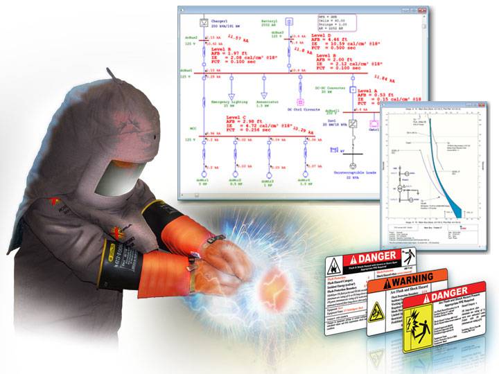
Arc-Flash Hazard Calculation Study When you first attempt to perform the arc flash study, it can seem quite intimidating. Even with the help of commercially In addition to the incident energy calculations, a distance known as the arc-flash boundary (AFB) must also be determined. The AFB defines

worker study matrixti

arc flash analysis software trace calc elec
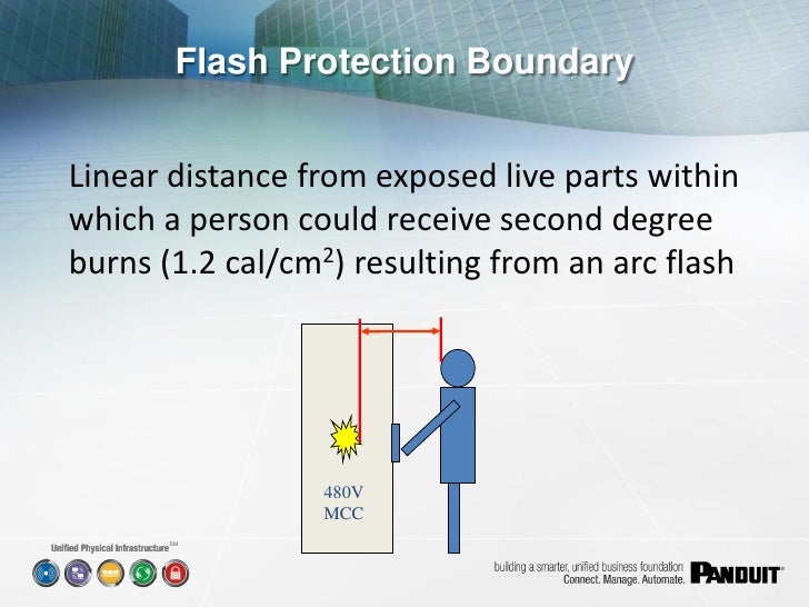
The arc flash boundary is an approach limit at a distance from exposed live parts or enclosed live parts if operation, manipulation, or testing of equipment creates a potential flash hazard, within which a person could receive a second degree burn if an electrical arc flash were to occur.

approach energized nfpa 70e boundaries conductors protection reduces alternating
Arc-flash boundaries are required around electrical equipment such as switchboards, panelboards, industrial control panels, motor control centers The only practical way of determining this boundary is to calculate the magnitude of the arc (a function of the available short circuit current), estimate
An Arc Flash Study or Analysis is a calculation performed by Professional Engineers to determine the incident energy found at each location which determines the various arc flash boundaries and what personal protective equipment (PPE) must be used in approaching each boundary.
Learn how to calculate arc flash incident energy extensively according to the standards of IEEE 1584-2018 here! To determine the final arcing current, incident energy, and arc-flash boundary at a specific voltage, first, we need to calculate the intermediate values for the three voltage levels of
The document provides empirical formulas for determining arc flash values known as incident energy, and arc flash boundaries. The time-current curves of upstream protective devices are the major factor in determining how long an arc-fault will last.
Arc flash calculations can tell us a great deal about how the system will behave during a fault condition. Annex D introduces five sets of equations to calculate the arc flash boundary and/or the incident energy level. Then use table (b) to determine PPE.
arc flash software analysis study etap line diagram labels ppe tcc calculation curves equipment program
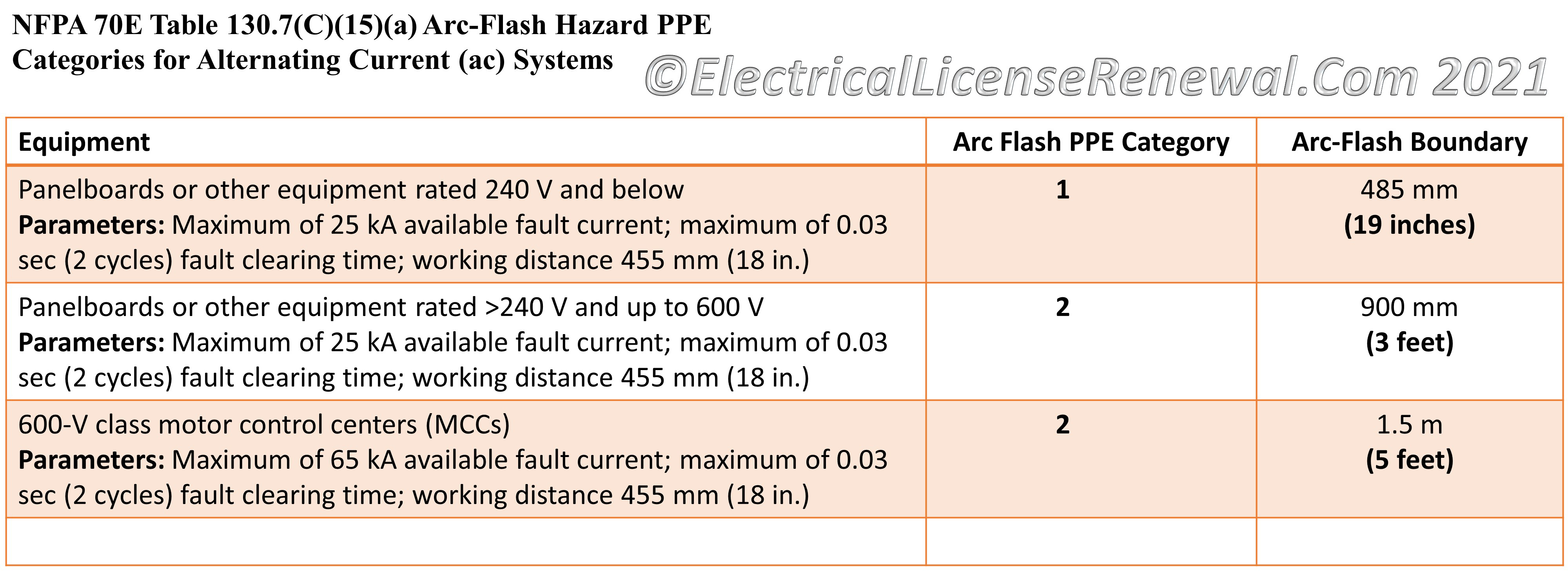
nfpa 70e ppe 130 arc flash categories electrical table ac hazard alternating systems current nec continuing courses education
Three factors determine the severity of an arc flash injury Approach / Protection Boundaries The National Fire Protection Association (NFPA) has developed specific approach boundaries designed to protect employees while working on or near energized equipment.
The AFB must be determined as part of an arc flash risk assessment and a requirement for arc flash labels. It can be calculated using an equation defined This example illustrates how to calculate the AFB for the 480-volt (V) panel that has been used for this series. I calculated the normalized
An Arc Flash Study or Analysis is a calculation performed by Professional Engineers to determine the incident energy found at each location which determines the various arc flash boundaries and what Personal Protective Equipment (PPE) must be used in approaching each boundary.
The following steps show how to accomplish this: ETAP Arc Flash has typical equipment gap and Once you have selected the equipment type, select typical gap and boundary values by clicking To change the Arc Flash Analysis Data and Shock Hazard Analysis Data press the "Data Options" button.
Flash protection boundary Arc-flash boundaries are required around electrical equipment such as switchboards, panelboards The only practical way of determining this boundary is to calculate the magnitude of the arc (a function of the available short circuit current), estimate how long the arc

nfpa 70e boundaries astm labeling determine netaworldjournal
The standard provides two options for determining the arc flash boundary distance and PPE requirements: the table method and the engineering analysis method. NFPA 70E 2015 includes task-based tables that can be used to determine when arc flash risks exist and what PPE should be used.
incident energy and flash boundaries. By: Dr. Mohamed A. Ali. 3. Determine bolted fault currents. 5. Determine protective device characteristics and duration of arcs. The time-current curves (TCCs) of upstream protective devices are the major factor in determining how long an arc-fault will last.
An Arc Flash is an electrical explosion resulting from a low impedance connection to ground or another voltage phase in an electrical system. This typically results in the complete destruction of equipment involved and severe injury or death to people inside the arc flash boundary at the time of the incident.

An Arc Flash Study or Analysis is a calculation performed by Professional Engineer to determine the incident energy found at each location which determines the various arc flash boundaries and what personal protective equipment (PPE) must be used in approaching each boundary.
This determines the arc flash bound-ary, the incident energy at the work-ing distance, and the level This arc flash label indicates that the breaker settings used in Figure 2 result in conditions that reduce the boundary This in-cludes how the electrical equipment. is maintained, operated, and modi-fied.
2. How do how do I create Arc Flash Labels, what is required, and where can I get help? We have created a paper that outlines the steps that must be #5 - This is the limited approach boundary*. An unqualified person has to be at least the distance listed or farther away from the energized equipment.
ARC FLASH: A short circuit through air that flashes over from one exposed live conductor to another conductor or to ground. This electrical fault can create a dangerous release of energy, including thermal energy, acoustical energy, pressure wave or debris. How Can an Arc Flash Occur?
Arc Flash Boundary: • Designed to prevent 2nd. degree burns when unprotected during an arc determine a second degree burn threshold relationship. Electrical arc flash boundaries. • Arc Flash Protection Boundary: When an arc flash hazard exists, an approach limit at a
How to Calculate the Arc Flash Boundary. Calculating an arc flash boundary is going to be based on the voltage of the equipment that would cause the arc flash. The exact method of calculation is different for AC and DC systems as well, so it is critical to have this information available.
The flash protection boundary is the distance at which staff without personal protective equipment (PPE) may suffer second-degree injuries that can be Determined exclusively on the system nominal voltage. NFPA 70E - arc flash boundary. The theoretical maximum arc power in MW is
How to perform arc flash risk assessment under NFPA 70e. NFPA code 70e helps firefighters calculate and maintain a safe boundary when dealing with flashovers. Arc flash - also often called a flashover - is a type of strong electrical explosion that poses a serious threat to firefighters when dealing
Arc Flash Boundary. This boundary is a distance at which a worker could suffer a 2nd-degree burn in 1 second to exposed bare skin. This method uses a set of tables to determine what the estimated arc flash energy and arc flash boundary are going to be.
The arc flash boundary is a vital metric to figuring out how far away your employees must be before they don their personal protective equipment (PPE). A simplified calculator is available for specifics, and differing methods are available for determining the arc flash boundary.
The arc flash blog is designed to help facility managers and maintenance professionals understand and If you're looking for the quickest and easiest way how to calculate the arc flash boundary then you've come to the right place! Dc is what we are trying to determine… the arc flash boundary.
The Arc Flash Boundary determines the distance from the equipment at which the Incident Energy of an arc flash would be cal/cm². The Flash Protection Boundary is the calculated safe working distance from electrical equipment which would not expose the employee to the hazards
Calculate Arc Flash Boundary and Arc Flash Incident Energy with the Free Arc Flash Calculator. Step 1: Leave the default time value, and click on Calculate. Step 2: Use the calculated arcing current Iarc to determine the actual fault clearing time for your protection system
